DTI Resolver interface User Manual
Overview
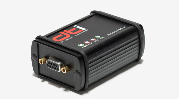
To make our system more universal, you can use a resolver interface which is directly connected to the inverter. The interface is a complete 12-bit resolution tracking resolver-to-digital converter. There are applications where you have to use a resolver to measure the correct position. Read the manual carefully and thoroughly before using the controller. If you have any questions, please contact us at support@drivetraininnovaton.com
Main features
- Incremental encoder emulation outputs is in standard A-quad-B format.
- UART communication interface for absolute position measurement
- System fault detection
- All digital I/O is differential (I/O + and - signals)
Specifications
- Supply:
- Voltage: 5V (4.75 V to 5.25 V)
- Maximum current: 300mA
- Excitation Frequency: 20 kHz (optional on request 10, 12, 15 kHz)
- Absolute 12-bit angular position
- Input Signal Range: 3.15 V p-p ± 27% (Sin and Cos)
- Maximum speed rating: 60,000 rpm
- Digital I/O voltage range: 5V
Connections
Resolver Connector Pinout
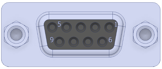
Harness side connector type: HARTING 09670095604
D-Sub Backshells: HARTING 09670090442
| Pin | Name | Description |
|---|---|---|
| 1 | TEMP | Motor temperature sensor |
| 2 | COS | Positive analog input of differential Cos/CosLO pair |
| 3 | DCOS_LO | Negative analog input of differential Cos/CosLO pair |
| 4 | SIN | Positive analog input of differential Sin/SinLO pair |
| 5 | SIN_LO | Negative analog input of differential Sin/SinLO pair |
| 6 | TEMP_GND | Motor temperature sensor ground |
| 7 | GND | Ground |
| 8 | EXC_LO | Excitiation frequency complement, analog output |
| 9 | PEXC | Excitiation frequency, analog output |
Communication connector pinout
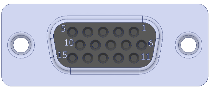
| Pin | Name | Description |
|---|---|---|
| 1 | DATA- | ABI encoder „DATA” differential signal negative |
| 2 | CLK- | ABI encoder „CLK” differential signal negative |
| 3 | A- | ABI encoder „A” differential signal negative |
| 4 | B- | ABI encoder „B” differential signal negative |
| 5 | NM- | ABI encoder „NM” differential signal negative |
| 6 | DATA+ | ABI encoder „DATA” differential signal positive |
| 7 | CLK+ | ABI encoder „CLK” differential signal positive |
| 8 | A+ | ABI encoder „A” differential signal positive |
| 9 | B+ | ABI encoder „B” differential signal positive |
| 10 | NM+ | ABI encoder „Z” differential signal positive |
| 11 | GND | Groung |
| 12 | GND | Ground |
| 13 | 5V_IN | 5V input, max 750 mW |
| 14 | TEMP_GND | Temperature sensor ground |
| 15 | TEMP | Temperature sensor |
LED indicators
There are 4 LEDs on the interface surface. Two status LEDs and two error LEDs.
Status LEDs
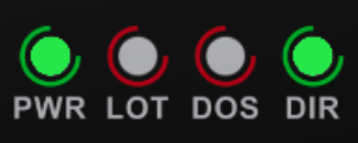
| LED | Description |
|---|---|
| PWR | This indicator should illuminate when the device is working. If this LED is not light, please check the communication connector. |
| DIR | This LED indicate the resolver rotation direction. If this led does not clearly indicate the direction, please check the resolver connector. If verything fine with the connector or wiring, please check the resolver. |
Error LEDs
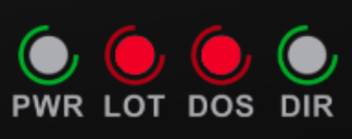
| LOT LED | DOS LED | |
|---|---|---|
| Loss of signal Loss of signal (LOS) is detected when either resolver input (Sin or Cos) falls below 2.24 V p-p |
ON | ON |
| Degradation of signal Degradation of signal is detected when either resolver input (Sin or Cos) exceeds 4.09 V p-p |
ON | OFF |
| Loss of tracking Loss of tracking is detected when the internal error signal exceeds 5° or the input signal exceeds the maximum tracking rate (1250 rps) |
OFF | ON |
| No fault | OFF | OFF |