Configuration
Modifying parameters
Any parameter changes are stored locally until the Write button is pressed to upload them to the controller.
To discard local changes and restore the current controller configuration, open the Configuration menu at the top and select the Read command. This action re-downloads the parameters from the controller and overwrites the locally stored values on the PC.
Motor parameters
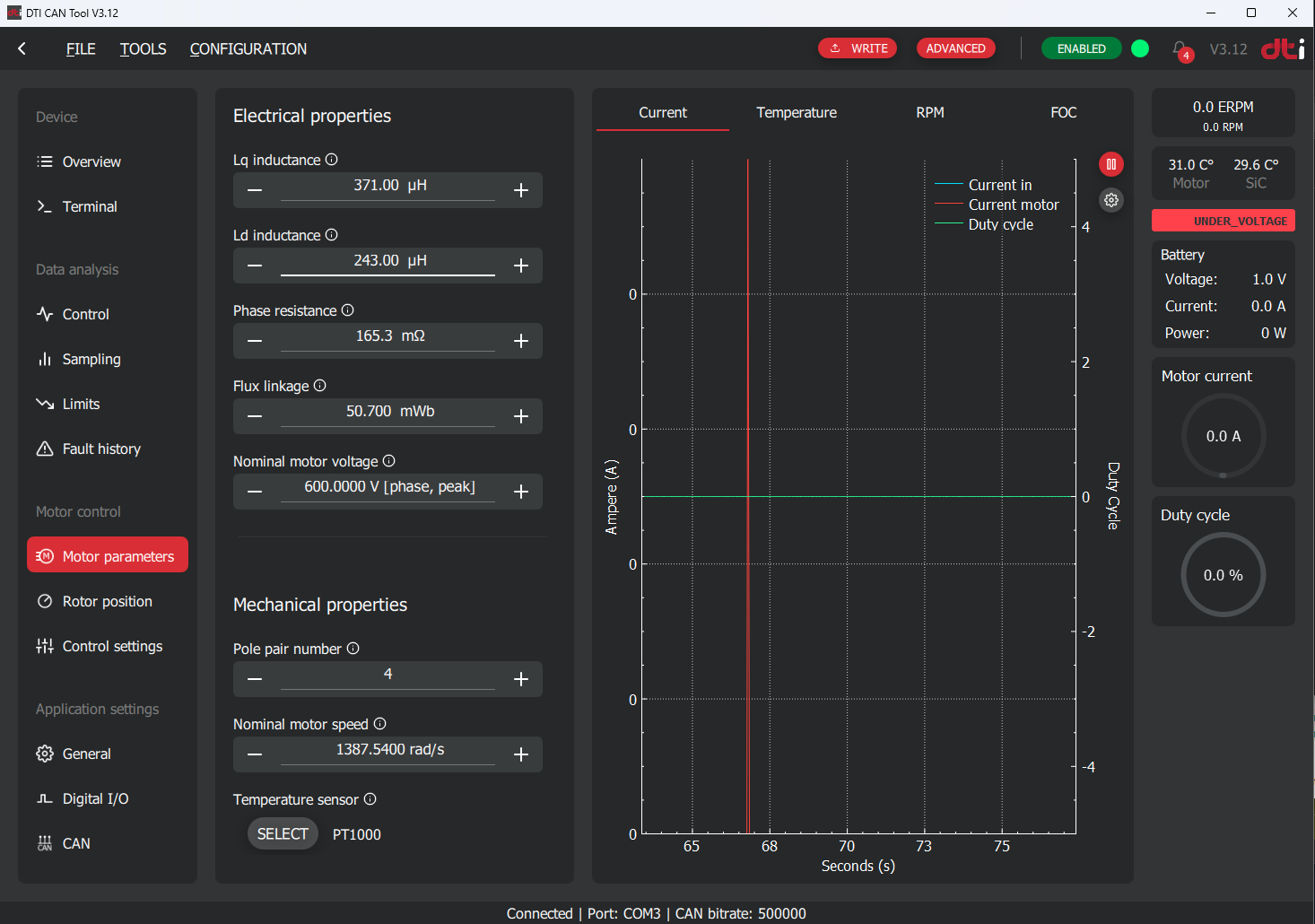
It is very important to configure correct motor parameters. These settings are the base of the motor control FOC algorithm. If the parameters are not correct the motor cannot be operated properly or inverter and/or motor can be damaged. The correct motor parameters can be obtained from the following sources:
- Recommended by DTI support service
- Electric motor datasheet or recommended by motor manufacturer
- Individual measurements done by the customer
We recommend to use the motor parameters provided by the DTI support service if available.
Motor parameters obtained from different source
If the motor paramaters are obtained from different sources than DTI, we recommend to validate the current control correctness before going into production. Current control quality can be determined by executing open loop and closed loop active sampling which initate a step response. Analyzing the step response result is mandatory to obtain information of the quality of the current control. If you need such a process, please contact support@drivetraininnovation.com.
Recommended motor parameters
DTI F-MOT:
- Lq inductance: 371 uH
- Ld inductance: 243 uH
- Phase resistance: 165,3 mOhm
- Flux linkage: 50,7 mWb
- Pole pair number: 4
- Nominal motor speed: 1387,54 rad/s
- Temperature sensor: PT1000
As a default the DTI F-SIC pre-loaded with the F-MOT parameters. If these are lost, you are able to restore it in the Configuration → Read default config menu located at the top of the screen.
Rotor position
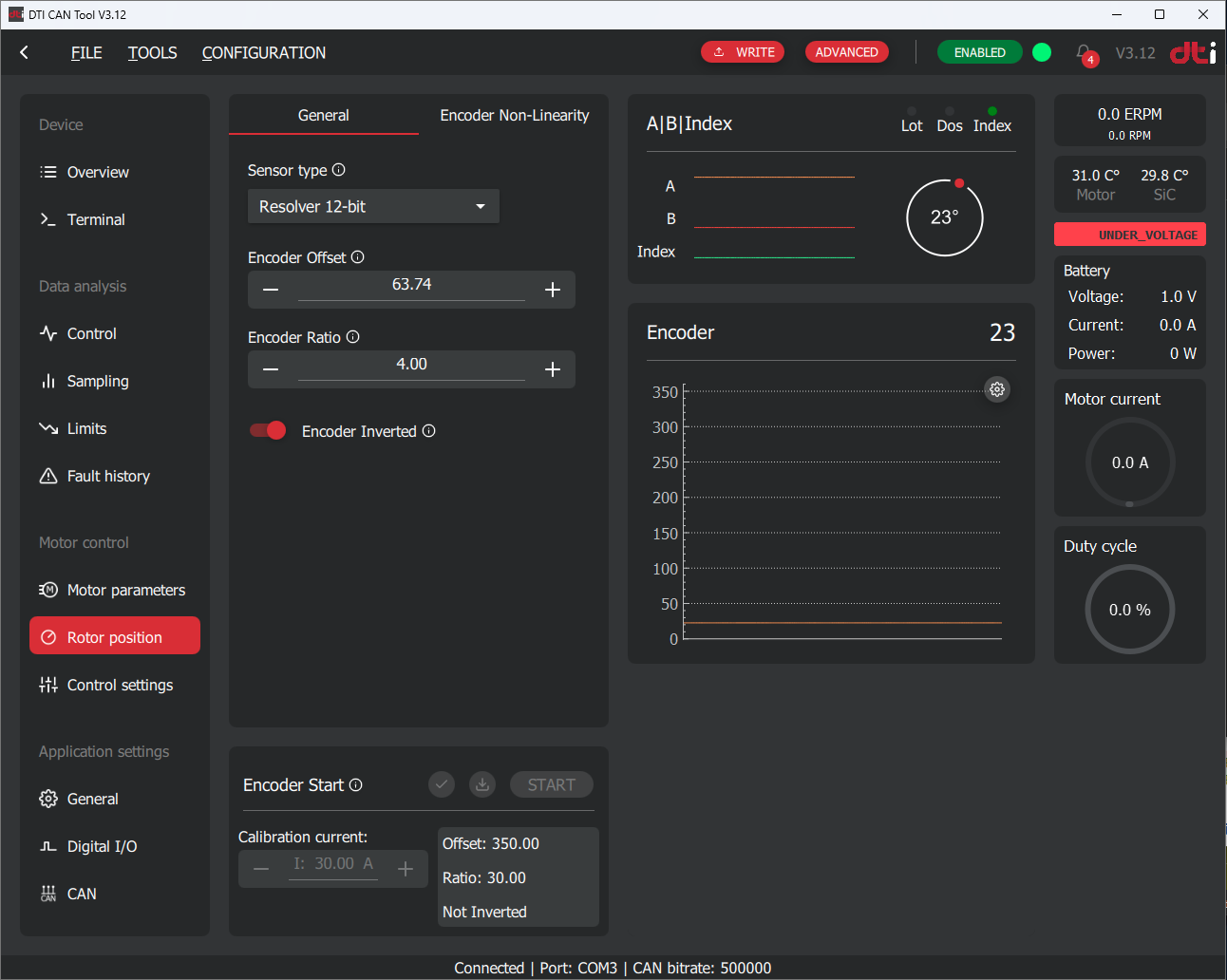
The rotor position is a key factor to maintain good quality and efficient FOC motor control. The following parameters must be set correctly:
- Sensor type
- Encoder offset
- Encoder ratio
- Encoder inverted
The sensor type must be selected according to the position sensor used. In the case of F-MOT select Resolver 12-bit. The encoder offset, ratio and inverted parameters are determined by the automatic calibration procedure. Do not run calibration yet — all other parameters must be verified first. This is described in the commissioning procedures.
Control settings
General tab

Invert motor direction
After the automatic rotor position calibration procedure the motor will turn CW or CCW for positive current targets depending on the phase cables connected. This parameter can invert the direction of the rotation of the motor. This setting is depending on the application. Generally, this parameter must be set that the vehicle must go forward for positive current targets.
Switching frequency
This parameter adjusts the switching frequency of the inverter. This impacts the sampling frequency, which is the update frequency of the PWM duties. From firmware v7.2 onwards, the sampling frequency equals the switching frequency. In firmware v7.1 the sampling frequency was twice the switching frequency. Increasing this number will reduce current ripple of the motor, but introduce switching losses and vice versa. The switching frequency also impacts other parameters of the controlling. Only change this parameter if you have a specific reason to do that or recommended by DTI support.
Fault stop time
When an unexpected event happens during the operation of the controller a fault code will became active. The fault code will remain active while the fault is still persistent. The fault code will be cleared automatically after the "Fault stop time" passed and fault is not persistent anymore. For details on how the fault system operates, see Fault system.
MFW mode
With the help of this parameter you can activate or deactivate MTPA1 or/and MFW2 motor control methods. For a description of how MTPA and MFW operate, see MTPA and field weakening. We recommend to spin the motor without MTPA and MFW for the first time. Enable them through the tests step by step to ensure proper operation.
Reference ramp parameters
This paramater can enable or disable reference ramping. Reference ramping helps to avoid quick changes in the current target which may lead to oscillations in current control loop.
Current ramp factor
The defined maximum current change in the reference in A/s. The smaller the number the slower the reaction time of the motor to the given reference.
Use reference ramp
It is highly recommended to use reference ramping to achieve a stable motor control below and beyond base speed in MFW region. Sudden reference changes in MFW region is avoidable. This function helps smoothen out and stabilize motor control.
Limit parameters tab
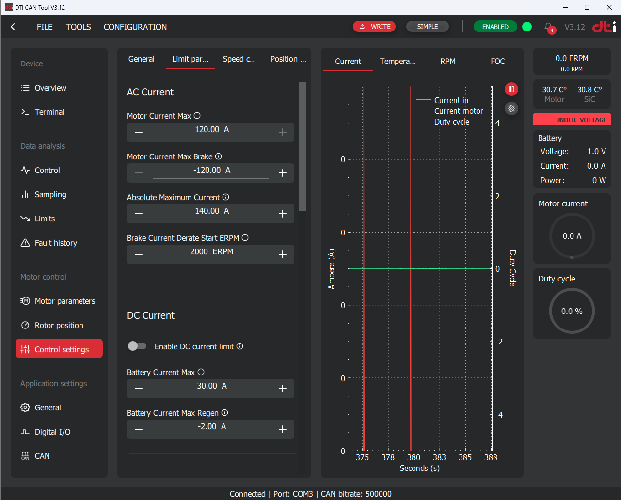
Motor current max
Determines the maximum AC current (Apk) which is allowed for the motor. The controller will ignore commanded value above this value.
Apk — not Arms
All AC current parameters on this page use peak amperes (Apk), not RMS amperes (Arms). A common mistake is entering the RMS value, which is approximately 29% lower than the peak value for a sinusoidal waveform (\(I_{rms} = I_{pk} / \sqrt{2} \approx 0.707 \cdot I_{pk}\)). Entering an Arms value will result in the motor being under-limited.
Motor current max brake
The maximum AC current used for braking the motor near to 0 RPM. This value is used when specifically a brake command is received by the controller.
Absolute maximum current
This AC current is used for activate the "Absolute maximum motor current" fault. This is a safety feature to protect the motor from overcurrent situation. This fault also can be activated when unsufficiend current control loop is incorrectly tuned. Make this parameter at least 20A more than the "Motor current max" parameter.
Brake current derate start ERPM
This parameter only used for the brake command. Beyond this ERPM the controller will decrease the brake current reference internally in order to slow down the motor smoothly and prevent oscillation at near 0 RPM. This is neccessary due to the low back-emf at low speeds.
DC current limit
Relevant parameters:
- Enable DC current limit: Enables or disables DC current limitation. DC current limitation can be used for protecting the battery.
- Battery current max: The maximum amount of DC current can be drained from the battery.
- Battery current max regen: The maximum amount of DC current can be fed to the battery.
The DC current limitation function operates by using a PI controller to maintain the DC input current within specified limits. The PI controller reduces the output AC current to ensure the DC current stays below the set thresholds.
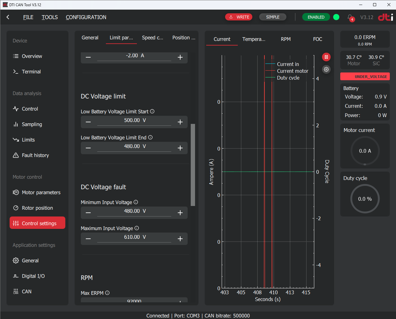
DC voltage limit
Relevant parameters:
- DC voltage limit start
- DC voltage limit end
The DC voltage limit is a limiting feature to protect the battery at low charging states. The DC voltage limit function derates the reference current linearly between the Start and End voltages. The DC voltage limit start is the voltage threshold where the AC current limiting starts. Above this voltage no limiting applied. Beyond DC voltage limit end voltage 0A target current allowed. When this limit active the power stage can be still active and motor control still allowed. This limit truncate the commanded current reference targeted by the user.
Example for operation:
- Voltage limit start is set to 200V
- Voltage limit end is set to 100V
This parameter must be determined according to the battery specification.
Minimum/Maximum input voltage
Relevant parameters:
- Minimum input voltage
- Maximum input voltage
When the HV voltage goes beyond or above the minimum or maximum voltage, a fault code will be activated immediately and remains active until the voltage recovers and Fault stop time passed after the recovery. Check Fault stop time section. Power stage will be inactivated immediately. Motor control not allowed until the conditions keeps the fault code active.

ERPM3 limit
Relevant parameters:
- Max ERPM
- Max ERPM reverse
- ERPM Limit start
ERPM limit is a limiting feature to protect the motor mechanically from overspin above its mechanical limit. The limit function truncates the commanded current reference as the following in function of ERPM:
- Above Max ERPM the commanded current reference truncated to 0A
- Between the Max ERPM and the (ERPM limit start * Max ERPM) region the current reference will be truncated linearly
- Below (ERPM limit start * Max ERPM) will not be truncated
Example for operation:
- Max ERPM: 10 000 EPRM
- ERPM limit start: 80%
The algorithm will start to truncate the commanded reference from (ERPM limit start * Max ERPM) in this case 8 000 ERPM:
The Max ERPM reverse functionality is the same like described above in the opposite rotation direction.
The Max ERPM and Max ERPM reverse parameter must be determined according to the motor datasheet or requirements of the application. We recommend to use 20% for the ERPM Limit start parameter as default value and change it as the application requires.
Power limit
Relevant parameters:
- Maximum wattage
- Maximum braking wattage
The power limit function maintains the DC input power within specified limits by adjusting the input to the DC PI current controller. The DC current limit is continuously calculated by dividing the "maximum wattage" by the input voltage. This calculated DC current is then used as the reference for the PI DC input current controller.
The same principle used for Maximum braking wattage.
To use this function the "Enable DC current limit" must be enabled.
Controller temperature limit
Relevant parameters:
- Controller temp cutoff start
- Controller temp cutoff end
The controller temperature limit function protects the semiconductor from overheating and damage. It linearly reduces the reference current between the Controller Temp Cutoff Start and Controller Temp Cutoff End temperature thresholds. The Controller Temp Cutoff Start is the temperature at which AC current limiting begins; below this threshold, no limiting is applied. Above the Controller Temp Cutoff End temperature, the target current is set to 0A. When this limit is active, the power stage remains operational, and motor control is still permitted. This function reduces the user-commanded current reference as needed.
Motor Temperature Limit
Relevant Parameters:
- Motor Temp Cutoff Start
- Motor Temp Cutoff End
The motor temperature limit function protects the motor from overheating and damage. It linearly reduces the reference current between the Motor Temp Cutoff Start and Motor Temp Cutoff End temperature thresholds. The Motor Temp Cutoff Start is the temperature at which AC current limiting begins; below this threshold, no limiting is applied. Above the Motor Temp Cutoff End temperature, the target current is set to 0A. When this limit is active, the power stage remains operational, and motor control is still permitted. This function reduces the user-commanded current reference as needed.
General settings
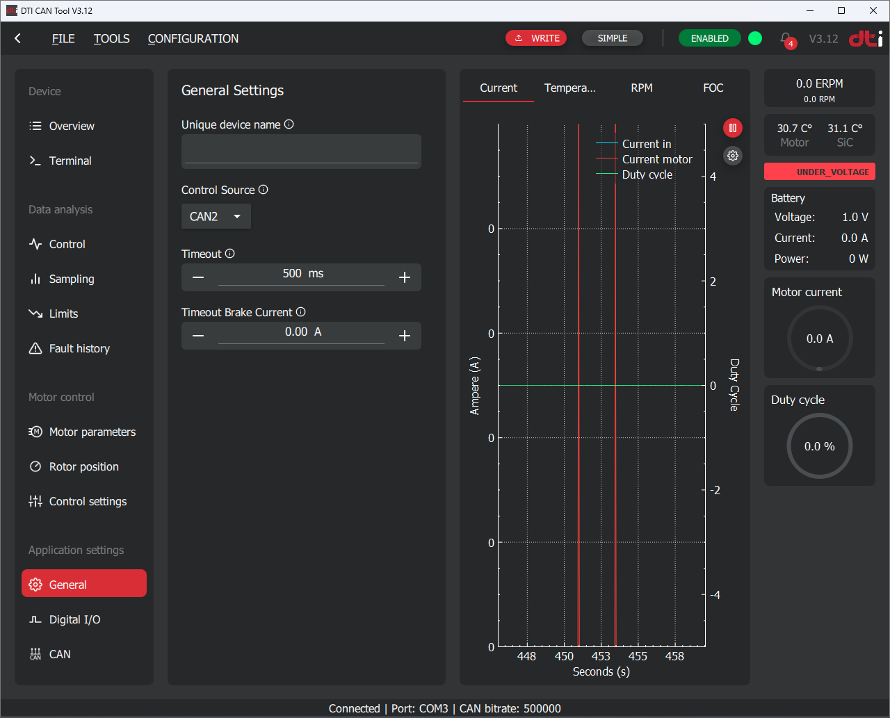
Unique device name
You can assign a custom alias to a specific device to make it easier to identify during node scanning. The assigned name will be displayed in the node scan results (e.g., "Front Left Drive").
Control source
Determines which source the controller accepts commands:
- CAN1: used by the GUI to control the motor during test setups. Not intend to use in production.
- CAN2: must be used by the user to send commands to the controller
We recommend to use CAN2 as a control source in production. Use CAN1 only on test benches or during encoder offset calibration procedure.
Timeout
If no command is received within the configured Timeout period, the controller will initiate braking using the predefined Timeout Brake Current parameter until the motor speed reaches zero. Once the speed is zero, the power stage will be switched off.
If the Timeout Brake Current is set to zero, the controller will override the target current to 0A, allowing the motor to coast freely. In this case, the power stage will be switched off as soon as possible (the shutdown may be delayed if the motor is operating in the field-weakening range).
Timeout brake current
Defines the braking current applied when a Timeout event occurs. If set to zero, the motor will not be actively braked.
CAN bus settings
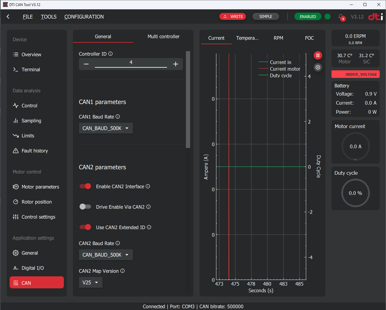
Controller ID
The Node ID of the controller used for the GUI to identify each controller and used for CAN2 to address each device.
CAN1 baud rate
Determines the CAN bus baudrate used for CAN1 interface. We recommend to keep at default 500kbps rate. Only change if you have a specific reason for that.
Enable CAN2 interface
Enables or disables the CAN2 interface operation.
Enabling CAN2 interaface
When the CAN2 interface is enabled and the configuration is saved, the controller must be restarted by performing a power cycle on the LV 12V supply in order to activate the CAN2 interface.
Drive enable via CAN2
This parameter enables monitoring of the Drive Enable signal via the CAN2 interface.
By default, the Drive Enable signal is interpreted as FALSE, preventing the drive from operating until a command message is received periodically in accordance with the selected protocol version.
When using the CAN2 interface to control the inverter, the Drive Enable message does not need to be sent continuously. It is sufficient to send the Drive Enable message once, and then continue transmitting control commands (e.g., AC current, speed control, braking), which will reset the timeout.
If no control message is received within the timeout period, the system will disable the Drive Enable state. After such a timeout event, a new Drive Enable message must be sent before control commands are accepted again.
Use CAN2 extended ID
Determines whether standard or extended CAN message ID will be used on CAN2 interface.
CAN2 baud rate
Determines the CAN bus baudrate used for CAN2 interface. We recommend to keep at default 500kbps rate. Only change if you have a specific reason for that.
CAN2 map version
DTI continuously develops the CAN2 message map to extend monitoring and control functionality for the user. To maintain compatibility with existing systems, the appropriate CAN2 message map version must be selected.
Digital I/O
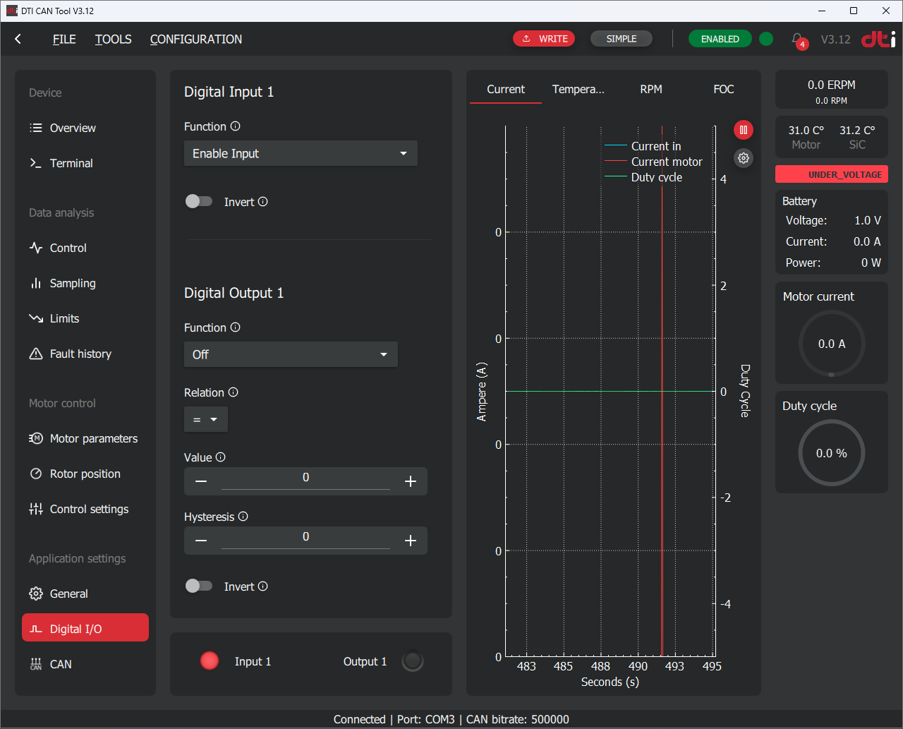
Digital input
Each digital input can be assigned a function by selecting it from the dropdown list.
By default, Digital Input 1 is configured as the Drive Enable input to prevent unintended motor operation. The Drive Enable signal is activated by pulling the corresponding digital input to ground. Signal interpretation can be inverted using the Invert parameter.
If the Drive Enable function is assigned, the signal must be active in order to perform any motor control operation. When the Drive Enable signal is inactive, the controller will reject all control commands.
The Drive Enable signal state can be monitored via the GUI located in the top right corner.
Digital output
Each digital output can be assigned a function by selecting it from the dropdown list.
Digital outputs can be used to extend the functionality of the controller by operating auxiliary devices such as pumps, fans, or relays. Each function has dedicated configuration parameters that must be set correctly according to the user's requirements.
-
MTPA — Maximum Torque Per Ampere. A control strategy used in electric drives to achieve the highest possible torque output for a given current. It optimizes efficiency by minimizing copper losses in the motor windings. ↩
-
MFW — Magnetizing Flux Weakening. A method applied at high speeds to reduce the effective magnetic flux in the motor. This allows operation beyond the base speed while preventing overvoltage conditions. ↩
-
ERPM = Mechanical RPM * Motor pole pair number ↩