Setup procedures
The following procedures must be carried out in the order listed. Each step builds on the previous one.
Prerequisites
Before starting any setup step, ensure the following conditions are met.
Hardware
- Motor mechanically installed and shaft free to rotate
- Phase cables connected to the inverter
- Position sensor (resolver) connected and wired correctly
- HV supply available and within the configured minimum/maximum voltage range
- LV 12 V supply connected to the inverter
Controller configuration
- Motor parameters configured — see Motor parameters
- Limit parameters set correctly for the application — see Limit parameters tab
- DC current limit disabled
- MFW Mode set to None
CAN2 setup
The closed loop step response (Step 2) requires a CAN2 command source. Complete the CAN2 operation section before proceeding, then return here.
- CAN2 interface enabled and controller rebooted
- CAN2 wiring connected and terminated
- CAN2 command decoding verified in DTI CAN Tool terminal
flowchart TD
    A[Configure motor parameters] --> B[Verify rotor position sensor]
    B --> C[Open loop step response]
    C --> D{Response valid?}
    D -- No --> E[Adjust motor parameters]
    E --> C
    D -- Yes --> F[Encoder offset calibration]
    F --> G[Initial slow rotation]
    G --> H[Closed loop step response]
    H --> I{Response valid?}
    I -- No --> J[Adjust motor parameters]
    J --> H
    I -- Yes --> K[Encoder nonlinearity calibration]
    K --> L[Enable MTPA only]
    L --> M[Rotate motor, small load, passive sampling]
    M --> N{Faults / noise?}
    N -- Yes --> O[Investigate and resolve]
    O --> M
    N -- No --> P[Ramp to 2/3 base speed\nVerify CAN stability]
    P --> Q{OK?}
    Q -- No --> O
    Q -- Yes --> R[Enable MTPA + MFW]
    R --> S[Incremental MFW speed steps\nstop between each]
    S --> T{Max RPM reached?}
    T -- No --> S
    T -- Yes --> U[Setup complete]
Step 1 — Verify rotor position sensor
The rotor position sensor signal must be verified by manually rotating the rotor before any motor operation or calibration is attempted.
Follow the instructions below:
- Ensure that the resolver is properly connected to the inverter.
- On the right-center side of the DTI CAN Tool screen, observe the current rotor angle (displayed in the center of the white circle) in real time. Note the initial angle.
- Carefully rotate the rotor by hand or with a suitable tool through exactly one full mechanical revolution. Mark the rotor before rotation to assist with positioning.
- While rotating, observe the change of the angle displayed in the DTI CAN Tool.
- After one full rotation, record the final angle shown in the GUI.
- Compare the initial angle (Step 2) with the final angle (Step 5). They must be identical or within ±1°. If so, the verification is successful.
This procedure ensures that the controller interprets a single mechanical turn as a single electrical turn. If this mapping is incorrect, motor operation will fail.
If the verification fails, identify and resolve the root cause. Based on experience, the following checklist can assist in troubleshooting:
- Verify all cables, connectors, and pinouts for wiring errors or misalignment.
- Confirm that the resolver is installed correctly from a mechanical perspective.
- Ensure that the resolver has one pole pair.
Most motor control issues can be traced to implausible or incorrect position sensor signals. We strongly recommend performing thorough double-checks of both the mechanical installation and the electrical wiring of the position sensor to ensure reliable operation.
Step 2 — FOC current controller validation
When to perform this procedure
This procedure is required when integrating an unknown third-party motor, or as a diagnostic step when the system is not operating correctly and additional information is needed for troubleshooting. For the DTI F-MOT motor, DTI has performed extensive validation testing, so correct operation can be assumed when using the published motor parameters. This procedure does not need to be repeated for every DTI F-MOT unit.
Background
For a detailed description of the FOC current controller and how motor parameters affect its behavior, see FOC current control.
Before performing any current controller validation, verify that the following motor parameters are correctly configured:
| Parameter | Description |
|---|---|
| L_d | D-axis inductance |
| L_q | Q-axis inductance |
| Flux linkage | Permanent magnet flux linkage (λ_pm) |
The PI current controller gains are computed automatically by the inverter firmware based on these parameters. Incorrect values will therefore result in a mistuned controller, not just a static operating point error.
Datasheet vs. real parameters
Motor datasheet parameters may differ from the actual values due to manufacturing tolerances, magnetic saturation, or temperature effects. The step response tests described below help identify parameter mismatches before full operation.
DTI provides an Active Sampling function in DTI CAN Tool (Sampling → Active Sampling) that injects a current step into the controller and records the transient response. Two injection modes are available:
| Mode | Description |
|---|---|
| Open loop | Step injected without position sensor feedback. Motor remains stationary. No encoder offset calibration required. |
| Closed loop | Step injected with position sensor feedback, superimposed on an externally commanded current target. Requires encoder offset calibration. |
When operating a motor with unvalidated parameters for the first time, both tests must be performed in the following order.
Open loop step response
The open loop test validates the current controller without rotating the motor. It is safe to perform before encoder calibration and is the recommended first diagnostic step on a new assembly.
Do not rotate the motor shaft during open loop testing
External rotation of the shaft during an open loop test is not recommended and may damage the inverter. For best results, mechanically fix the shaft or ensure the highest possible load inertia is present on it before starting the test.
Prerequisites:
- No active faults
- No active limits
- Motor parameters configured
- Enable signal (if configured)
- In Control Settings, Reference Ramp temporarily disabled (re-enable after validation)
- In Control Settings, MFW Mode set to None
- In General, Control Source set to CAN1
Procedure:
-
In Sampling → Active Sampling, click Open Loop. The inverter injects the configured current step and records the response automatically.
-
Click Download to retrieve the recorded sample to the PC.
-
Select the sample from the list to open the waveform view. Inspect the step response visually.
What to look for
A well-tuned response shows a fast rise with minimal overshoot and no sustained oscillation. Significant overshoot or ringing indicates incorrect L_d/L_q values. A slow, sluggish response may indicate parameters that are too high.
Closed loop step response
The closed loop test validates current controller performance under active position feedback with the motor rotating. It must be performed after encoder offset calibration.
Prerequisites:
- No active faults
- No active limits
- Enable signal (if configured)
- Encoder offset calibration completed
- External CAN2 command source available and configured
- In Control Settings, Reference Ramp temporarily disabled (re-enable after validation)
- In Control Settings, MFW Mode set to None
- In General, Control Source set to CAN2, desired current command applied from external source
Procedure:
-
In Sampling → Active Sampling, click Closed Loop. The inverter superimposes the configured step onto the active current command and records the response.
-
Click Download to retrieve the recorded sample to the PC.
-
Select the sample from the list to open the waveform view. Inspect the step response visually.
-
Repeat at a minimum of 4 operating points distributed evenly across the base speed range, starting from the lowest RPM and progressing to higher values. Operation in the field weakening region is not permitted during this test. No load on the motor is required — free rotation is sufficient.
What to look for
The same criteria apply as in the open loop test. Additionally, verify that the d-axis and q-axis responses are well-decoupled — cross-coupling between axes indicates a flux linkage or inductance mismatch.
Recommended step current for DTI F-MOT
Use a step injection current of 10 A when testing with the DTI F-MOT.
Re-enable Reference Ramp
After completing both validation steps, ensure the Reference Ramp is re-enabled in Control Settings before returning to normal operation.
Step 3 — Encoder offset calibration
Encoder offset
In Field-Oriented Control (FOC), the Encoder Offset is a critical parameter. It defines the alignment between the rotor's actual magnetic field position and the controller's electrical reference frame.
Accurate calibration of the Encoder Offset is essential to ensure proper torque production, smooth operation, and high efficiency. An incorrect or uncalibrated offset may lead to poor performance, excessive current consumption, vibrations, or even unstable motor operation.
For reliable FOC operation, the Encoder Offset must be calibrated carefully and verified before enabling motor control. Do not operate the motor with uncalibrated encoder offset.
Calibration procedure
DTI inverters are equipped with an automatic encoder offset calibration procedure, which can be initiated from the GUI once all prerequisites are met. The procedure takes approximately 2–4 minutes, during which the motor shaft will move and may produce buzzing or clicking noises.
The encoder offset calibration must be performed once after installing the rotor position sensor. The resulting values are stored in the controller's flash memory for future use.
Warning
The offset calibration procedure is critical for reliable Field-Oriented Control (FOC) operation. It must be performed again if the calibration values are lost or if the rotor position sensor becomes loose from its mounting. Even small shifts of the position sensor can severely reduce efficiency, increase losses, or cause unstable motor behavior. Always re-calibrate if there is any doubt about the correctness of the encoder offset. Running the calibration ensures safe and efficient motor operation.
Calibration prerequisites
Before initiating the offset calibration procedure, ensure that the following conditions are met:
- The Drive Enable signal is active if it is configured as a digital input or transmitted via CAN2. This can be monitored in the top-right corner of the GUI.
- No active faults are present.
- The rotor position sensor functionality has been validated according to the procedure described in Step 1 — Verify rotor position sensor.
- The HV input voltage is sufficient to clear any Undervoltage faults.
- The rotor shaft is able to move freely without any mechanical load.
- The correct sensor type is selected.
- No limits are active. This can be verified in the Limits menu, where all limit indicators must display 0%.
- No commands are being transmitted via the CAN2 interface. For the calibration process, it is recommended to temporarily switch the control source to CAN1 and revert once calibration is complete.
Executing the calibration
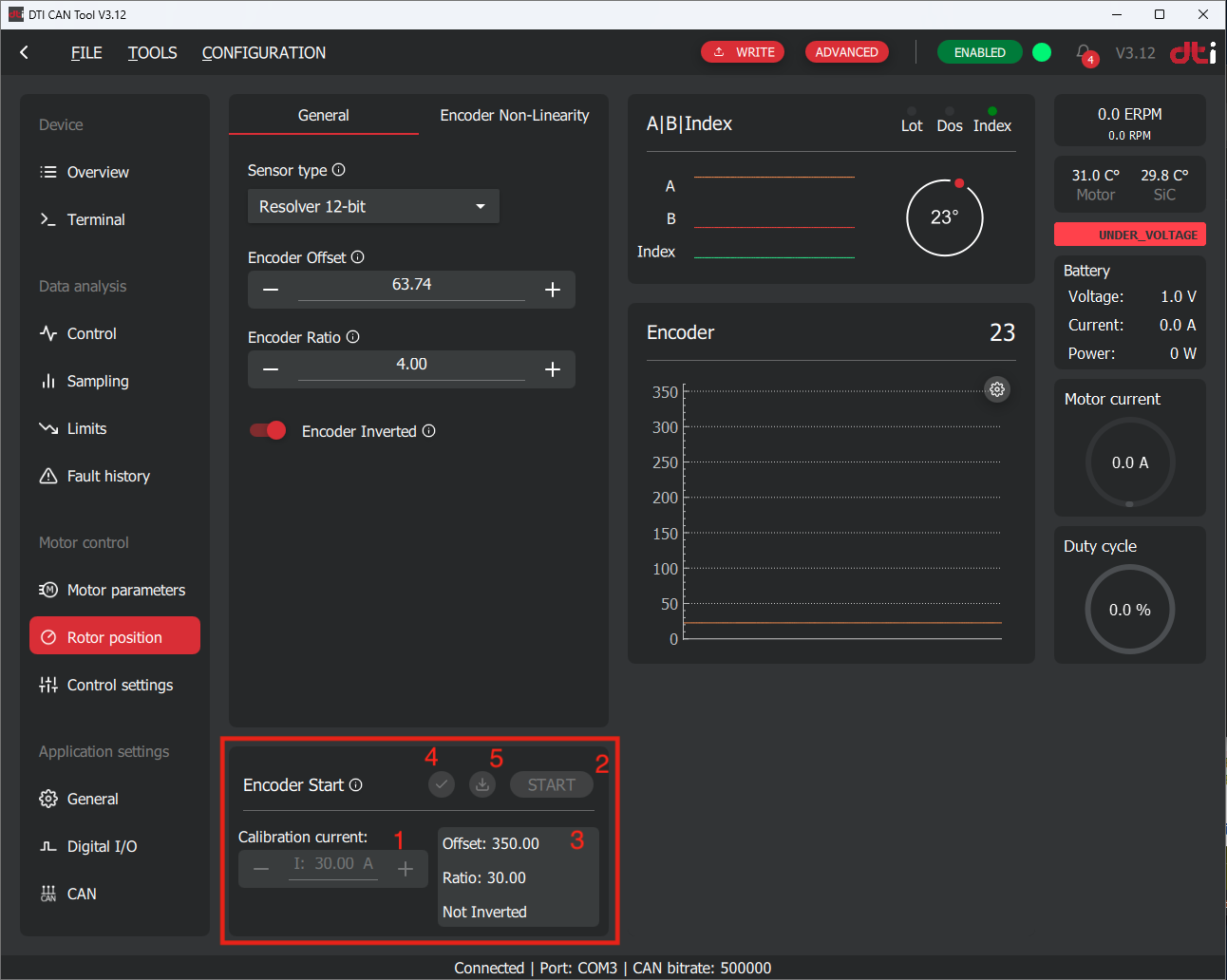
Once the conditions above are met, the calibration procedure can be started by following the instructions:
- Enter the calibration current into the input field labeled 1. For DTI F-MOT we recommend to use 10A.
- Start the calibration procedure by clicking the Start button labeled 2.
The procedure takes approximately 2–4 minutes, during which the motor shaft will move and may produce buzzing or clicking noises. During the process, do not block the rotor shaft and wait until finish.
Failure
In the event of any malfunction, the calibration process can be safely interrupted by switching off the controller's low-voltage power supply.
In case of an emergency situation, the high-voltage supply must be disconnected immediately.
When the calibration process is complete, the GUI displays a green notification bar at the bottom of the screen and automatically downloads the calibration results. The results are presented in the fields labeled 3.
The calibration procedure will result determining of these parameters:
- Encoder offset
- Encoder ratio
- Encoder inverted
Each of the above parameters must be correct in order to operate the motor properly. You must verify them before applying it into the configuration:
- Encoder offset: Must be in between 0-359 degree
- Encoder ratio: Must indicate the pole pair number of the motor. In case of DTI F-MOT motor the encoder ratio must be 4. (only in case of resolvers with 1 pole pairs)
- Encoder inverted: can be true or false. No additional check needed.
Tip
It is strongly recommended to perform the encoder calibration procedure at least three times consecutively.
Calculate the average of the resulting encoder offsets and use this value for the configuration.
If deviations greater than 5° are observed between calibration runs, increase the calibration current by 50%.
If the issue persists, please contact our support team at support@drivetraininnovation.com.
The results can be copied directly using the checkmark button labeled 4.
In the unlikely event that the results are not downloaded automatically, they can be retrieved manually using the download button labeled 5.
Finishing calibration
When the calibration process described above has been completed and the results have been copied into the configuration, press the Write button to upload the parameters to the controller.
After the upload is successful, the changes take effect immediately, and the calibration procedure is considered complete.
Step 4 — Encoder nonlinearity calibration
Encoder nonlinearity
The angle signal provided by the rotor position sensor (resolver or magnetic encoder) contains a periodic, systematic error. Its sources can be mechanical (shaft eccentricity, ellipticity), magnetic (non-uniform pole pitch of the encoder ring), or signal-processing in nature (sin/cos amplitude mismatch, DC offset, quadrature non-orthogonality). This error manifests as integer harmonics of the mechanical rotation period (1×, 2×, and higher orders per revolution). In FOC, the consequence is direct torque ripple and higher-harmonic current distortion, because the d–q transformation operates on an incorrect rotor angle.
Without nonlinearity calibration, the following effects are expected:
| Effect | Description |
|---|---|
| Motor operation | Motor remains operational, but with degraded performance |
| Torque quality | Increased torque ripple |
| Current quality | Increased DC and AC current ripple |
| Power dissipation | Higher inverter losses due to AC current ripple |
Compensating position sensor nonlinearity
DTI provides a calibration procedure to measure and compensate the position sensor nonlinearity, thereby reducing its effect on torque ripple.
Prerequisites:
- Verified position sensor operation
- Validated motor parameters and confirmed correct current controller operation (the published DTI F-MOT parameters are considered validated by DTI)
- Encoder offset calibration is not mandatory but is recommended prior to performing nonlinearity calibration
Procedure:
-
Rotate the motor at a stable RPM — at least half the maximum operating speed. Using an external drive source is strongly recommended. If the motor must be driven by the inverter itself, be aware that existing torque ripple (caused by the uncorrected nonlinearity) may distort the measured curve.
-
Capture a sample once the speed has stabilized: trigger the passive sampling function in DTI CAN Tool, then download the recorded data to the PC using the Download button.
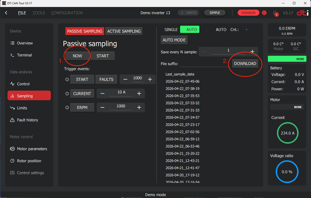
Capturing and downloading a sample with DTI CAN Tool. (1) Trigger passive sampling. (2) Download the captured sample to the PC. -
Open the nonlinearity tab: navigate to Rotor Position → Encoder Nonlinearity in the GUI.
-
Load the sample file captured in the previous step.
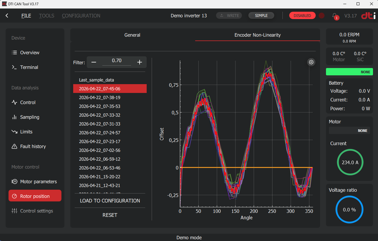
Loading the captured nonlinearity curve. -
Evaluate the nonlinearity curve. The GUI displays each individual rotation as a thin colored line and their average as a thick red line.
Curve validation
Only apply a nonlinearity correction if the displayed curve is valid. A valid curve resembles a smooth sinusoidal shape and closes on itself (start and end points meet). A curve that does not close or shows an irregular, non-sinusoidal shape indicates a faulty measurement — do not apply it.
The averaging strength is controlled by the filter coefficient: a value closer to 1 produces weaker averaging (individual rotations have more weight), while a value closer to 0 produces stronger averaging. The default value is recommended for most applications.
Example of an invalid nonlinearity curve:
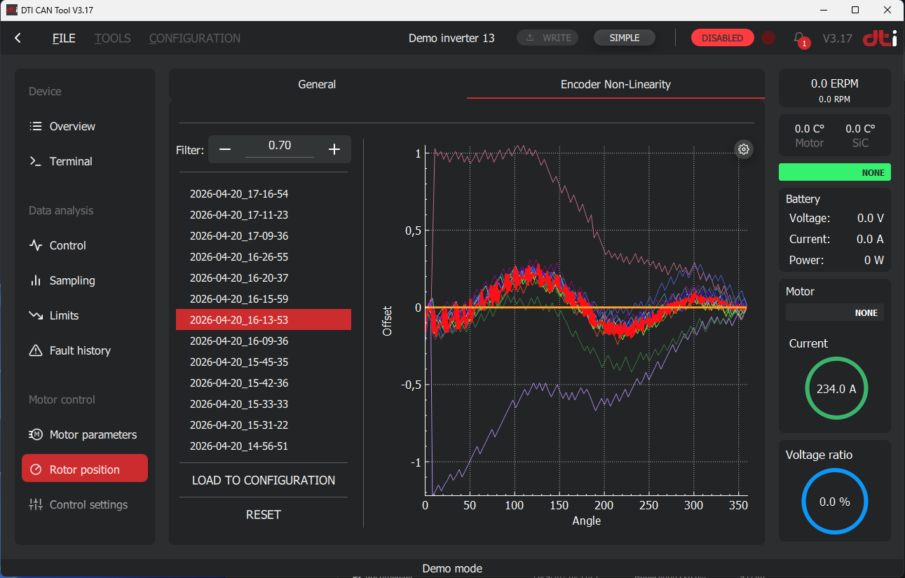
Example of an invalid nonlinearity curve — the curve is not closed and does not resemble a sinusoidal shape. -
Apply the curve: click Load to configuration. The applied correction curve is shown as a thick orange line overlaid on the measured data. Click the Write button in the top bar to save the changes to the inverter.
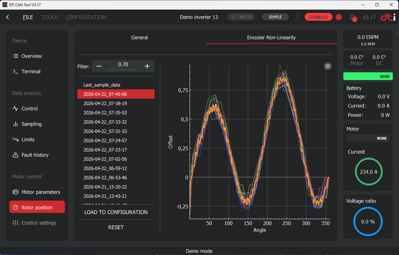
Applied nonlinearity correction curve (orange) overlaid on the measured average (red). -
Verify the result: reload the sample file to confirm the applied (orange) curve matches the measured average (red line).
-
To remove the correction at any time, click Reset and then Write.
Measurement reliability
It is recommended to capture at least 2–3 independent samples and compare the resulting curves. Good agreement between samples confirms measurement validity and helps identify outliers caused by speed instability or external disturbances.
Recalibration is required whenever:
- The position sensor is mechanically disassembled or repositioned
- The sensor type or resolution is changed
- The motor is replaced
Assembly dependency
The nonlinearity correction is specific to a given mechanical assembly. Even minor mechanical changes — such as re-seating the encoder ring — can alter the nonlinearity characteristic and necessitate recalibration.
Step 5 — Enable MTPA and field weakening
Enable MTPA and MFW incrementally — not simultaneously — to isolate any issues that may arise. A battery is recommended as the DC source for field weakening testing.
Prerequisites:
- Encoder offset calibration completed
- Encoder nonlinearity calibration completed (recommended)
- Reference Ramp enabled
Phase 1 — MTPA validation
-
In Control Settings → General, set MFW Mode to MTPA only.
-
Rotate the motor. A small mechanical load may be applied if available. Use passive sampling in DTI CAN Tool to monitor the current waveforms during operation.
-
Verify that no faults are active and no abnormal mechanical noise is present. Current consumption should decrease compared to None mode for the same torque output — this confirms MTPA is operating correctly.
-
Gradually ramp up to approximately 2/3 of base speed. Verify CAN communication stability: commands must be received reliably and the motor must follow the reference without unexpected behavior.
-
If any fault, oscillation, or abnormal noise is observed, stop immediately, investigate, and resolve before continuing.
Phase 2 — Field weakening validation
Use a battery as DC source
A battery (not a power supply) is recommended for field weakening testing, as the regenerative current during deceleration may exceed the absorption capacity of a bench power supply.
-
Set MFW Mode to MTPA + MFW.
-
Increase the current target gradually to raise motor speed into the field weakening region. Use incremental speed targets: ramp up to a target MFW speed, then remove the current target and allow the motor to stop completely before proceeding to the next higher target.
Example sequence for DTI F-MOT
- Ramp up slowly to 15 000 RPM → remove target → stop
- Ramp up slowly to 17 000 RPM → remove target → stop
- Ramp up slowly to 19 000 RPM → remove target → stop
- Continue in similar increments until the desired maximum speed is reached
-
At each speed point, capture a passive sample in DTI CAN Tool and inspect the waveforms. Verify that the d-axis current returns cleanly to zero when the current target is removed — this confirms correct field weakening exit behavior.
-
Monitor DC bus current and motor temperature at each step.
-
If instability is observed (oscillations, overcurrent faults), reduce the maximum speed, re-check motor parameters, and contact DTI support if the issue persists.
Reference Ramp in the MFW region
Ensure the Reference Ramp remains enabled throughout field weakening operation. Sudden current reference changes in the MFW region can cause instability.
CAN2 operation
Parameters to set
To control the motor via CAN2 interface you must enter the parameters as following in Application settings -> CAN menu:
- Enable CAN2 interface: Must be enabled. Perform reboot, after write.
- Drive enable via CAN2: Can be disabled. Depends on user requirements.
- Use CAN2 extended ID: Make it enabled, for demonstration purposes we use extended id. User can override it according their requirements.
- CAN2 baud rate: Set it to 500kbps. We recommend to use 500kbps or lower. Only use 1Mbit if you have a special reason to do that.
- CAN2 map version: Select V25, for demonstration purposes. User can override it according their requirements.
- By default, every message is configured for broadcasting with a 25 ms period. For demonstration and testing purposes, it is recommended to keep this default setting. If this is not the case, configure at least one message with a 100 ms broadcast period. This can be done by selecting the appropriate CAN2 map, navigating to the V25-specific variables, and assigning a 100 ms broadcast period to one of the messages.
Navigate to the Application settings -> General menu and set the following:
- Control source: Set it to CAN2.
- Timeout: Set to 500 ms. Can be overriden by the user according to their requirements.
After setting the parameters above, the CAN2 interface is ready for the operation from the view of the controller.
CAN2 Wiring
To control the F-SIC with external ECU or PCAN-USB the CAN2 high and low lines must be correctly wired up and terminated according to the Low voltage wiring section.
Verification of CAN2 Command Decoding
You can monitor the received commands value on the controller. This helps the troubleshooting and integration process.
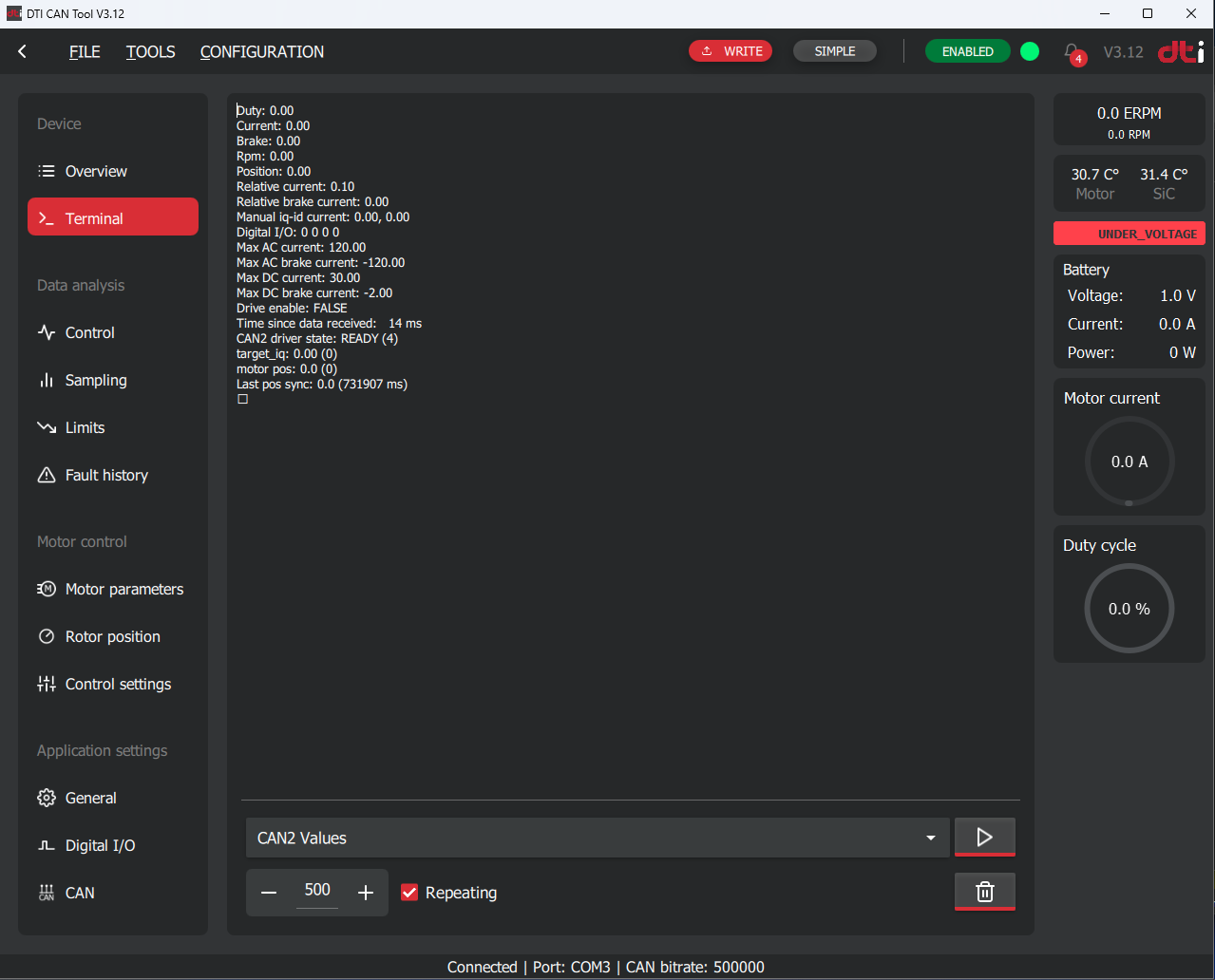
Go to Device → Terminal and select CAN2 values from the list at the bottom.
Enable the Repeating checkbox and press the Play button. The terminal will then continuously update the display area, where each line represents a command value received by the inverter. For further details on the available commands, refer to the CAN2 Manual.
When transmitting a specific command, you can verify whether the controller decodes it correctly before enabling active operation. It is strongly recommended to validate proper decoding in order to prevent unexpected and potentially hazardous motor behavior.
The Time since data received counter indicates the elapsed time since the last valid command was received. Please note that if the Control source is set to anything other than CAN2, this timer will not reset and will continue counting.
Sending CAN2 commands to the inverter
The controller is designed to be commanded by the VCU of the user. This VCU calculates the neccessary current reference and forward it to the motor controller via CAN2 interface. Due to the fact that each system of the users are different, this guide will demonstrate the commanding procedure using PCAN-USB device and PCAN-View software.
Note
PCAN-USB is a USB-to-CAN interface device developed by PEAK-System. It enables a PC to connect directly to a CAN network, providing both sending and receiving capabilities for CAN messages.
PCAN-View is the diagnostic and monitoring software supplied with PCAN interfaces. It allows users to send, receive, and log CAN messages in real time, making it useful for testing, debugging, and verifying CAN communication. You can download it from the website of PEAK-System.
Connect the PCAN-USB tool to the phisycal CAN bus and to the PC. Firstly, you must install the device driver to your computer.
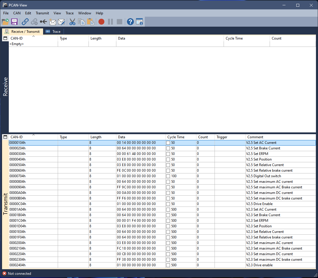
Install and open the PCAN-View software and click to the connect button 3rd from the left located on the top toolbox of the screen. When connected the CAN bus messages broadcasted by the controller will be shown in the receive screen if the controller has any messages configured to be broadcasted and wiring is correct.
Check the appropiate CAN2 protocol manual and implement it into the transmit area by defining CAN ID, length and data. Set the broadcast period at least 2 times faster than defined it in the Timeout parameter. We recommend to use 50ms of Cycle time.
The message implementations can be downloaded from here and can be imported into the PCAN-View. This example made for Node Id 4. Make sure that your Controller id equal to 4 in order to decode and broadcast the messages properly for the demonstration.
Danger
Do NOT connect the high-voltage power supply to the inverter before verifying the command decoding.
An improper message implementation may cause the motor to spin up immediately to high speed, resulting in unexpected and potentially hazardous operation.
You can enable periodic command broadcasting in PCAN-View by selecting the corresponding Cycle Time checkbox in the transmit area. Once periodic transmission is active, the received command can be verified in the controller terminal as described in the section above.
If the V2.5 Set AC Current command is enabled, it defaults to broadcasting a current reference of 10.0 A. In the terminal under CAN2 values, the second line should display:
Current: 10.0
Modifying the data field of the transmitted message will update the displayed value accordingly. This provides a reliable method to verify the commands you intend to use.
After successful command verification, you can be confident that the message implementation is correct. We strongly recommend repeating the same verification procedure once the commands are integrated into the user's VCU to ensure proper and safe operation.
If command verification fails:
- Check wiring and connections.
- Verify message format, including endianness, data length, and field values.
- Refer to the CAN2 Manual for detailed message specifications.
If the command verification is still unsuccessful, please contact us at support@drivetraininnovation.com.
CAN2 commanding in production
If the verification process above is successful, the controller can be used in production with high voltage applied. We recommend to spin the motor with low current at the first time to make sure the operation is stable.