Wiring
Electric connections
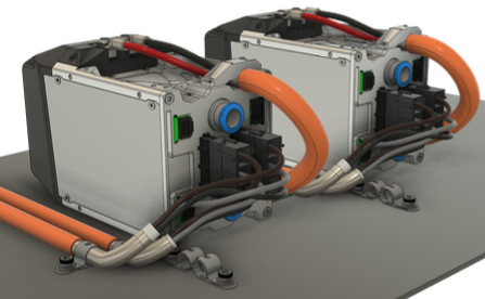
The F-SIC inverter has 4 types of electric connectors:
- High voltage DC connector
- High voltage AC connector
- Position sensor connector
- Low voltage connector
Each connector mus be wired up correctly in order to rotate the motor. In this guide only a single inverter motor spin will be introduced. These connectors located on the front panel of the device:
Low voltage wiring
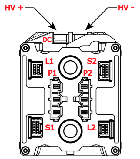
| Symbol | Description |
|---|---|
| DC | Common high voltage DC connector |
| L1 | 1st Low voltage connector |
| P1 | 1st High voltage AC connector |
| S1 | 1st position sensor connector |
| L2 | 2nd low voltage connector |
| P2 | 2nd high voltage AC connector |
| S2 | 2nd position sensor connector |
The suffix of each connector symbol indentifes the corresponding inverter.
The low voltage connector pins are identifed as follows:
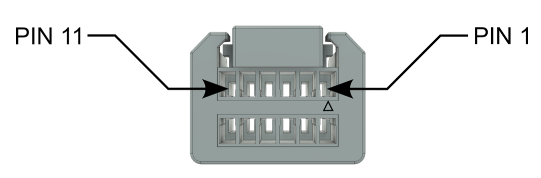
"L1" low voltage connector pinout:
| PIN | Description |
|---|---|
| 1 | 12_VIN |
| 12 | GND |
| 8 | CAN1_H |
| 6 | CAN1_L |
| 7 | CAN2_H |
| 5 | CAN2_L |
OBD diagnostic connector pinout:
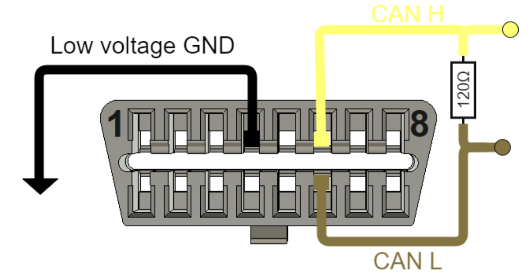
| PIN | Description |
|---|---|
| 4 | GND |
| 6 | CAN_H |
| 14 | CAN_L |
Connect the "L1" low voltage connector as the following:
- Pin 1 and 12: 12V power supply at least 2A current capability per inverter module (2 inverter modules per block)
- Pin 8 and 6: CAN1 to OBD connector
- Pin 7 and 5: CAN2 to your VCU (or PCAN-USB tool for test)
Low Voltage harness
For the S1 and S2 connectors we highly recommend to use PTFE insulated wires with maximum cross section of 28AWG to create roboust and stable wiring. Power lines ( 12_VIN and the corresponding power GND) should be routed as close as possible to each other. It is recommended to twist them together. Use the proper corresponding crimp tools when creating the wiring loom as improperly crimped wires or contact errors may casue various issues in the LV system.
Can bus topology
Use Daisy chain topology with as-short-as-possible stubs to establish reliable communication between the inverters (applies to CAN1 and CAN2).
CAN bus termination resistor
Connect 120 ohm termination resistor to both ends of the bus. There is a built in termination resistor in the F-SIC inverter, you can activate it with a dip switch under the lid. For more information please check F-SIC datasheet.
CAN1 interface is used for diagnostic connection to DTI CAN Tool for configuration. CAN2 interface can be used by the user to implement their command messages and monitoring for the traction system. This guide will demonstrate how to commanding the inverter with PCAN-USB with PCAN-View software.
Do not power up the low voltage system yet.
After connecting the low voltage connector the next step is to connect the resolver position sensor to the inverter.
Position sensor wiring
The position sensor pins are identifed as follows:
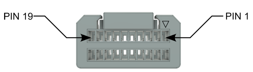
Wire up the position sensor as follows:
| S1 PIN | Description | F-MOT SENSOR PIN | Description |
|---|---|---|---|
| 10 | SIN+ | 1 | SIN1 signal |
| 12 | SIN- | 2 | SIN2 signal |
| 11 | COS+ | 3 | COS1 signal |
| 9 | COS- | 4 | COS2 signal |
| 13 | EXC+ | 5 | Excitation input |
| 15 | EXC- | 6 | Excitation input |
| 1 | Temp | 7 | Temp |
| 2 | Temp_GND | 8 | Temp |
Postion sensor shielding
Connect the DTI F-MOT position sensor cable shielding tightly to the low voltage ground of the inverter. Make sure that the grounding point is strong and has star topology. Proper shielding and ground is essential for proper inverter operation.
High voltage AC wiring
Connect the "P1" AC connector U, V, W pins to the DTI F-MOT U, V, W terminals with the proper connector on both ends:
- Inverter side: Molex Mini-Fit Sr. 428160312
- DTI F-MOT side: TE Connectivity 321827 M4 shoe terminal
Production harness
For detailed technical description about the proper electrical connection, please check the corresponding DTI F-SIC and DTI F-MOT datasheets!
High voltage DC wiring
Connect the HV+ and HV- terminals to a 48V test battery, ensuring correct polarity, as no reverse polarity protection is provided. DTI strongly recommends incorporating a fuse in the HV line for enhanced safety. A precharge system between the inverter and the battery is mandatory to prevent potential damage to the inverter. Failure to implement a proper precharge system may result in inverter damage! This test configuration is strictly limited to "no load" testing and integration procedures.
Power supply
Power supplies are not suitable as a primary energy source, as they cannot manage transients generated by regenerative braking. High-voltage transients exceeding 600V may cause damage to the inverter and/or motor.
When testing with the 48V test battery, the Maximum input voltage parameter must be configured to 60V to safeguard the hardware against overvoltage spikes in the event of a fault.
Grounding
You must create a strong and star topology low voltage potential grounding point for the traction system. You must connect the following lines here:
- Shielding of the position sensor cable
- Shielding of the high voltage AC cable
- Upright/Motor casings (with at least 4mm2 wire)
- Low voltage system ground
- Inverter casing
It is recommend to use a metal base plate as a common grounding point. The inverters can be mechanically fixed to this plate.
Bench tests
Building a properly grounded and shielded system is a MUST even if the setup is not meant to be built to it’s final location/compartment, if this step is not properly carried out, instability,communication errors, connection issues and potentially damages in the system may cause.
DTI Diagnostics tool
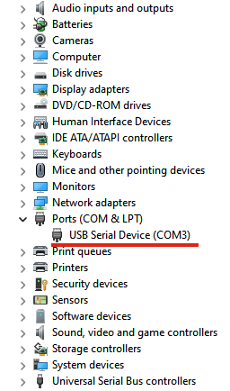
The DTI Diagnostics tool is a USB-CAN converter device which can translate CAN messages into a Lawicel protocol which is represented as a virtual serial port (COM port) in the system. No additional driver required. Any operation system should recognize it without additional actions.
Connect the DTI diagnostic tool into the OBD port and into the PC. Check the device manager if it recognized as a serial port.
If the device does not recognized try the followings:
- Click the "Scan for hardware changes button"
- Reboot the computer
- Try a different USB port
- Try to plug it into a different PC
If none of the options has success, contact us at support@drivetraininnovation.com